Chapter Two: Studio Gear
3. Microphones | Page 5
Common Multiple Microphone Patterns for Stereo Recording
Stereophonic sound, or simply stereo recording, was developed in the early 1930s by Alan Blumlein in England and, independently, by Harvey Fletcher in the US. The concept was to record and then recreate the sound panorama as we naturally hear it using the localization cues discussed in the previous chapter. True stereo, meaning a stereo image not created artificially through mono-sourced panning manipulation, requires two or more microphones, often a stereo pair (meaning the mics are at least the same pattern, if not model), or two or more mics set to different patterns, like the M-S stereo below. Because of their arrangement, these patterns may register a differentiated time of arrival, a differentiated sound pressure level or amplitude, and differentiated phase relationships for off-axis elements of the source. In this regard, these cues, which mimic the ITD and IID of hearing, create a sense of our "being there." Of course, these can be manipulated and altered either in real time or in the studio after the fact to make the image either "better," often the case with film soundtracks, or, in the worst cases, annoyingly unnatural and just plain wrong. It is not uncommon to hear recordings, say of a piano concerto, where the soloist, additionally recorded by a spot mic, seems to be placed yards in front of the orchestra. In the classic mic patterns below, one concern of engineers was that if the stereo or multi-mic image were to be combined into a mono image, the phase cancellation would cause a metallic comb filter effect. This is still a concern for the electronic musician who may take their stereo recording samples and use them in a mono form. And phase cancellation of frequencies due to the spacing of stereo mics is still a concern, even for a stereo mix, where time-delay phase correction is not possible due to off-axis spill into another mic channel.
This page does not cover recording or reinforcing individual instruments with multiple microphones. There are many excellent guides for that in print and on the web, and a few of them are listed on Page 6: Microphone Resources.
Common Stereo Mic Patterns (plus the three-mic Decca Tree) are:
X-Y Coincident | Near-Coincident and ORTF | Mid-Side (M-S) | Blumlein Pair | A-B Stereo and Spaced Pairs | Decca Tree
Plan view from above.
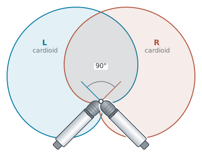
X-Y coincident pair: two cardioid microphones crossed at 90°, capsules stacked at a single point.
X-Y Coincident
X-Y coincident pair: two cardioid mics aimed across each other at an included angle between 90° and 135°, with the capsules as close to occupying the same point in space as possible, to accurately recreate the way a listener hears with directional cues. Once the capsules are separated by more than an inch or two, time-of-arrival differences begin to creep in, and the array is properly called near-coincident rather than coincident. X-Y capsules are normally stacked one directly above the other, with no horizontal space between them. This creates a more mono-compatible image, since the two channels differ only in level and not in arrival time, so nothing cancels when they are summed.
X-Y mic'ing creates an excellent stereo image when used fairly close to the source, but is not as convincing spatially at greater distances from the source. Since the mic capsules are so close, the stereo effect is created more by the off-axis sound pressure differences of the response patterns rather than time-of-arrival and phase discrimination. The most common polar pattern to use for X-Y mic'ing is the cardioid. Hyper- and supercardioids are also frequently used, particularly when less of the room is wanted in the pickup, but at a distance the narrower field can produce an undesirable hole-in-the-middle effect. When two figure-8 patterns are crossed at 90°, the array becomes the Blumlein pair described below. Where a pattern has a rear lobe, sound arriving from behind images in the opposite channel from where it actually sits.
A standard piece of studio gear is an X-Y (or stereo) bar that allows for two mics on a single stand with variable spacing. An added element of stereo separation would be an acoustic baffle between the mics, or an artificial head to simulate the HRTF, like the binaural mic mentioned previously.
Plan view from above.
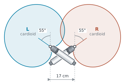
ORTF near-coincident pair: two cardioid microphones spaced 17 cm (about 6¾″) apart, each angled 55° off the center line for a 110° included angle.
Near-Coincident and ORTF
A second stereo pattern, the near-coincident pair, is similar to X-Y coincident, except the microphones face outward at 90°–135°. Cardioid, hyper-, and supercardioid mics may be used. One of the most well-used near-coincident patterns is the ORTF (Office de Radiodiffusion Télévision Française), whereby two cardioid microphones are spaced 17 cm (about 6¾″) apart and angled 110° apart, 55° off-center on each side. The technique produces a wider stereo image with less center than X-Y coincident, and because its spacing and splay already approximate a pair of ears on a head, it needs no physical baffle. It may experience some phase cancellation issues, particularly when summed to mono. However, like X-Y mic'ing, the stereo image is better differentiated at closer distances. Both of these methods capture less of the room ambience than spaced omnis, but often this is a good thing.
A variation of ORTF is NOS (Nederlandse Omroep Stichting) in which the mics are angled 90° apart but spaced about 30 cm (12″), which the Netherlands Broadcasting Foundation found captures more ambience than ORTF, but still has fewer phase problems than a widely spaced array. Other variants (usually small distance and/or angle differences) are RAI (21 cm / 8¼″, 100°), DIN (20 cm / 8″, 90°), and Olson (20 cm / 8″, 135°).
Plan view from above.
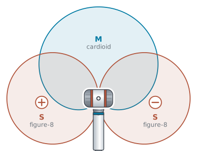
Mid-Side pair: a cardioid mid aimed at the source and a figure-8 side turned sideways, capsules stacked at a single point. The two side lobes are equally sensitive but opposite in polarity.
Mid-Side (M-S)
Another coincident mic'ing approach, one that has become popular relatively recently, is called M-S or Mid-Side. Here a bi-directional (figure-8) mic called the side and a cardioid mic called the mid are placed at right angles, with the figure-8 turned sideways so that its null faces the source and its two lobes face left and right (picking up more of the room), and the cardioid aimed straight down the middle at the source (picking up more direct sound). An M-S sum-and-difference decoder—now built into most DAWs as a plug-in, available as a hardware box, or set up on any mixer that can invert phase—takes the original figure-8 signal (labeled S+) and inverts it on another channel (labeled S−). S+ and S− are panned hard left and hard right respectively, while the mid (M) is panned center. This will yield M + S = left channel, and M − S = right channel. When combining the outputs of the two mics, the apparent width of the stereo field can be changed and the amount of direct sound vs. ambience can be adjusted after the fact in the studio by increasing or decreasing the amount of "side" vs. "mid." Producers also like M-S because summing the two channels gives (M + S) + (M − S) = 2M: the side signal cancels exactly, leaving a clean mono mix of the mid mic alone. A common variation of the above would be to use an omni as the mid mic. The sum-and-difference idea behind M-S was first described by Alan Blumlein in his 1931 patent, though M-S as a working studio technique is generally credited to the Danish engineer Holger Lauridsen in the early 1950s.
Plan view from above.
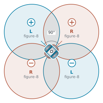
Blumlein pair: two figure-8 microphones crossed at 90°, capsules stacked at a single point. All four lobes are equally sensitive; the rear pair is opposite in polarity.
Blumlein Pair
Named for Alan Blumlein (a senior engineer at EMI's Central Research Laboratories in Hayes during the 1930s, and a pioneer in stereo audio), a Blumlein pair uses two coincident (i.e., one directly above the other) bi-directional (or figure-8) pattern microphones set up at 90° to each other, each one angled 45° off the center axis of the array. This stereo mic'ing technique provides a strong center image and good room ambience. Because the capsules are coincident, the two channels stay phase-coherent, so low frequencies sum cleanly instead of partially cancelling. In addition, the overlap in patterns means each mic's nulls fall exactly along the other mic's axis of maximum sensitivity, so nothing is missed.
In the area in front of the microphones, you have basically the same behavior as we saw with the coincident cardioid pair. Changes in the angle of incidence of the sound source change the inter-channel amplitude differences, resulting in simple pair-wise power panning. Note, however, that this pair is more sensitive to changes in angle, and therefore registers bigger swings in apparent source location than a pair of cardioids crossed at 90°. Sources at the rear left of the pair image to the right, and sources at the rear right image to the left, both with reversed polarity. Like the coincident patterns above, Blumlein becomes less convincing when placed too far from the source, and so additional outriggers are frequently used to cover wide ensembles rather than move the pair back. With the advent of surround patterns, some engineers have added a second rear-facing Blumlein pair on top of the forward-facing pair.
Plan view from above.
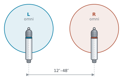
A-B spaced pair: two omnidirectional microphones parallel to the source, typically 12″–48″ (30 cm–1.2 m) apart.
A-B Stereo and Spaced Pairs
Some literature uses A-B stereo and spaced pair interchangeably, but here we will make a distinction.
A-B stereo recording, pioneered by Harvey Fletcher, places two mics more widely apart than coincident mic'ing, usually 12″–48″ (30 cm–1.2 m) and parallel to the source. More often than not, omni patterns are used, though any of the directional patterns can be used instead. The stereo image is created primarily by the difference in time of arrival (to a lesser degree, amplitude differences) between the mics of a side-to-side differentiated source, for example, specific orchestral instruments. It is a good technique to use for a very wide ensemble where the environmental ambience is also important. A-B stereo does not play well with mono mixdowns and is very susceptible to phase cancellations, particularly at low frequencies, although these differences contribute to the sensation of the stereo image.
A spaced pair, usually omnis, is also useful for either wide ensembles or where cross-talk between two or more sound sources is undesirable. The setup, which again is parallel to the source, can be quite wide. This is where you will often see the rule of 3:1 invoked, so it is worth knowing what it actually governs. The rule is about microphones on different sources: two mics should be at least three times as far apart as each one is from its own source, which keeps the sound leaking between them quiet enough to avoid audible comb filtering. It gets quoted for stereo pairs, but it was never meant for them—a pair 15 feet from an orchestra would have to be 45 feet apart, which would create a hole in the middle. Over a single ensemble you set the spacing by ear.
Plan view from above.
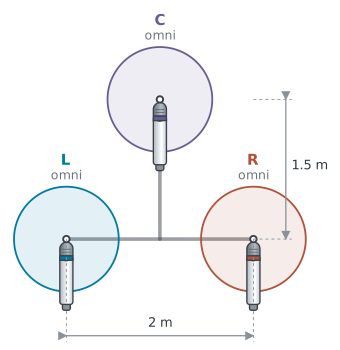
Decca Tree: three omnidirectional microphones on a T-bar, the rear pair 2 m (about 6½ ft) apart with the center mic 1.5 m (about 5 ft) forward.
Decca Tree
The Decca Tree was developed in the mid-1950s at the British Decca Record Company, whose recordings were issued in the US on the London label, as a better means of recording large ensembles, such as an orchestra. It gives a very wide, spacious, and mix-adjustable image, thanks to intensity, time, and phase cues. The T-shaped arrangement (which can be accomplished with either separate stands or a dedicated Decca Tree fixture) originally used three forward-facing mics—Neumann M49 cardioids at first, soon replaced by omnidirectional Neumann M 50s—pointed slightly inward and downward from high stands. Omnis suit the tree because even an omni becomes somewhat directional at high frequencies, and the M 50, with its capsule mounted on a sphere, is deliberately so. It is now also used with cardioids and other directionals, as well as with the rear pair angled slightly outward like the ORTF above. In fact, the center microphone exists precisely to fill the hole in the middle that a widely spaced pair leaves—the problem we just saw when the 3:1 rule is misapplied to a stereo pair. Standard placement of the tree is still quite high—roughly ten to twelve feet up—and just above or slightly behind the conductor. The spacing shown in the figure is important to avoid phasing issues, but the dimensions are not rigid: the 2 m width of the rear pair is a suggested minimum, and the center mic's forward offset commonly runs 1–1.5 m, with wider arrangements suitable for larger ensembles. It is common now to add an additional pair of wide outrigger omnis to the mix. Additional variations (shown to me by Konrad Strauss, longtime chair of IU's Department of Audio Engineering and Sound Production) involve cutting down the omni field of the rear mics with an acoustic baffle. You can see a variety of approaches, including the related five- or seven-mic Fukada Tree to record surround with similar arrangements here.
Stereo Pioneers
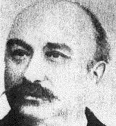
CLÉMENT ADER
French electrical and mechanical engineer Clément Ader developed the Paris telephone network in 1880. Shortly thereafter, he created the théâtrophone, which broadcast plays and operas from the Paris Opera using up to 80 telephone transmitters. First demonstrated at the Paris International Exposition of Electricity in 1881, it is widely credited as the first two-channel transmission, though strictly it was binaural—delivered to two ears rather than to two loudspeakers. The signals were mixed down to two channels and distributed through a network whereby listeners put a telephone receiver in each ear to hear the live event. Eventually, there were numerous subscribers who had dedicated boxes to hear the broadcasts up to several miles away from the Opera.
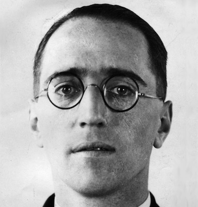
ALAN BLUMLEIN
Alan Blumlein was a remarkable British electrical engineer who, in the 1930s, pioneered much of the recording technology in use today. Credited as the "father" of stereo (originally called binaural sound), he explored spaced omnis separated by a baffle, which gave intensity differences above about 700 Hz, and built a "shuffling circuit" to convert the arrival-time differences below that into the intensity differences loudspeaker stereo needs. He devised the crossed pair, developed stereo record-cutting techniques, improved microphones, and much more—though with no figure-8 microphones available to him, the crossed pair that now carries his name appears in the 1931 patent as a claim rather than a built device. His inspiration was to improve the poor quality of sound in the cinema and have the sound follow the actors, which he accomplished. Sadly, he died in a wartime airplane crash in 1942 at the age of 38.
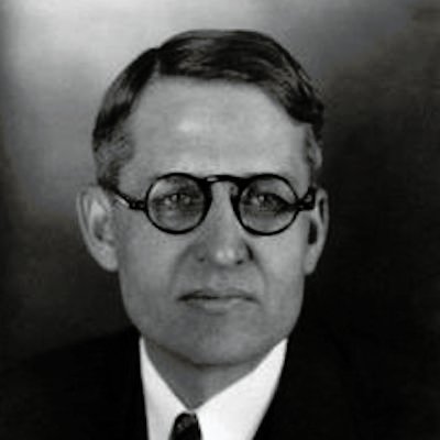
HARVEY FLETCHER
Harvey Fletcher, mentioned earlier for his pioneering work in psychoacoustics, was also working in the US on stereo-imaged sound in the 1930s. He worked with the Philadelphia Orchestra to both broadcast and record stereo-imaged sound, first in two channels and later in three. He explored spaced A-B arrays, using baffles—and eventually a dummy head—to approximate the shadowing of a real head and increase channel separation. At the 1933 Chicago World's Fair, he and Bell Labs set up a binaural dummy head named Oscar (a mic in each ear) in a glass booth. As someone walked around Oscar speaking, fairgoers outside the booth, listening on headphones, would hear the voice circle their own heads.
Image credit: Comb filter response (feedforward, negative gain) by Krishnavedala, via Wikimedia Commons, licensed CC BY-SA 3.0. Converted to PNG; otherwise unaltered.

