Chapter Three: MIDI

5. MIDI Data Format: Controller Change in Detail
Controller change data is where the real expressive power of MIDI comes into play. The data can be physically generated in real time from a MIDI instrument via the mod wheel, a pedal or keyboard sliders, or even from user-built data-driven devices, such as interactive Arduino-based interfaces, game controllers and the motion sensors in a phone. Programs like Chataigne can translate other forms of user-generated data, such as OSC or the output of a game controller, into MIDI controller messages. Even an ordinary webcam can become a controller: tools built on Google's MediaPipe hand-tracking library, such as the browser-based Handmate, turn hand position and gestures into MIDI controller data. Apps such as TouchOSC let you design your own control surface on a phone or tablet that sends either OSC or MIDI. Controller data can also be added manually while editing in a DAW to control virtual instruments and plug-ins.
Controllers are invoked by the controller change status byte (1011nnnn) followed by the controller number (0–127) followed by the controller value (0–127). The following chart shows one complete controller change message, in binary, hexadecimal and decimal, with the mod wheel turned all the way up to 127.
| Status Byte CC, Channel 1 |
Data Byte 1 Mod Wheel |
Data Byte 2 Value |
|
|---|---|---|---|
| Binary | 10110000 | 00000001 | 01111111 |
| Hex | B0 | 01 | 7F |
| Decimal | 176 | 1 | 127 |
Continuous Controller Data Stream
Because these messages often result in a dense stream of changing values, running status is crucial for data reduction. Many DAWs and sequencers can also thin out recorded controller data, reducing its density. The video, captured from a MIDI monitor app, shows the large stream of controller #1 (mod wheel) data on MIDI channel 1 generated by turning a mod wheel up slowly. The term continuous data also includes some non-controllers, such as Pitch Bend and Aftertouch—pretty much anything that results in a stream of values.
In viewing the list of controller change numbers, you will notice that certain numbers have been assigned to specific functions. The most important of these are:
| Ctrl # | Function |
|---|---|
| 1 | modulation wheel |
| 7 | channel volume |
| 10 | pan |
| 64 | sustain pedal |
In general, controllers 0–31 carry continuous data, such as mod wheel and volume, and 32–63 serve as their optional fine adjustments (see the Factoid below). Controllers 64–69 are switches (on/off), such as the sustain pedal. Controllers 70–119 are a mix of continuous sound and effects controllers (brightness, attack time, reverb depth and the like), a few special-purpose ones, and undefined numbers free for any use. Older conventions of switch values, such as any data value over 0 = 'ON,' or recognizing only 0 = 'OFF' and 127 = 'ON' and ignoring the rest, have been replaced by the convention 0–63 = 'OFF' and 64–127 = 'ON.' Some digital pianos, though, read the sustain pedal as continuous, so that values in between give a partial, or half-pedal, effect.
While the MIDI Specification suggests these 'default' uses, and most manufacturers have set the default for at least mod wheel, volume, panning and sustain pedal to respond to the specific numbers above, the actual response of an instrument is determined by the instrument's programming, which often can be altered. For example, while the instrument's default may be to use a sustain pedal to sustain a pitch, it may be reprogrammed to jump up an octave instead, or to do both at once. When programming synth/sampler patches, assigning a single controller to several parameters of a sound at once, such as having the mod wheel open a filter while it adds vibrato, is often a very powerful tool. In a DAW, the quickest way to make such an assignment is usually MIDI Learn: click the instrument or plug-in control you want, move a knob or slider on your controller, and the two are linked.
14-Bit Controllers
It is little known (and little used) that controllers 32–63 are reserved as an additional 7-bit LSB (least significant byte) for the corresponding controllers 0–31, creating 14-bit resolution (16,384 steps rather than 128) if desired, similar to Pitch Bend. The coarse controller moves the value in 128 large steps, and its fine partner divides each of those steps into 128 smaller ones. For example, controller #39 can be used as a fine adjustment of controller #7 (channel volume). The same is true for controller #33, which acts as an LSB for controller #1 (modulation wheel). Bank Select works the same way: controller #0 is the coarse byte and #32 the fine one. In MIDI 2.0, every controller has 32-bit resolution on its own, so the pairing isn't needed there.
Controllers 120–127 are reserved for channel mode messages, described in the next section.
Each narrow cell is one controller number, from 0 at the left to 127 at the right.
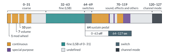
The map above shows how all 128 controller numbers are divided, with the four controllers to know marked. A complete list of the controller numbers assigned by the MIDI 1.0 specification appears on the next page.
